Programming DDS9850 dan Bentuk Sinyal Output
Jan15
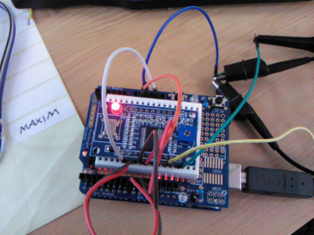
Dengan menggunakan arduino kita dapat mengatur frekuensi output dari DDS9850. Berikut adalah program yang dapat digunakan.
Output yang dihasilkan.

/* * A simple single freq AD9850 Arduino test script * Original AD9851 DDS sketch by Andrew Smallbone at www.rocketnumbernine.com * Modified for testing the inexpensive AD9850 ebay DDS modules * Pictures and pinouts at nr8o.dhlpilotcentral.com * 9850 datasheet at http://www.analog.com/static/imported-files/data_sheets/AD9850.pdf * Use freely */
#define W_CLK 8       // Pin 8 - connect to AD9850 module word load clock pin (CLK)
#define FQ_UD 9       // Pin 9 - connect to freq update pin (FQ)
#define DATA 10       // Pin 10 - connect to serial data load pin (DATA)
#define RESET 11      // Pin 11 - connect to reset pin (RST).
#define pulseHigh(pin)
{
digitalWrite(pin, HIGH);
digitalWrite(pin, LOW);
} // transfers a byte, a bit at a time, LSB first to the 9850 via serial DATA line
void tfr_byte(byte data)
{
for (int i=0; i<8; i++, data>>=1)
{
digitalWrite(DATA, data & 0x01);
pulseHigh(W_CLK);   //after each bit sent, CLK is pulsed high
}
} // frequency calc from datasheet page 8 = <sys clock> * <frequency tuning word>/2^32
void sendFrequency(double frequency)
{
int32_t freq = frequency * 4294967295/125000000;  // note 125 MHz clock on 9850 for (int b=0; b<4; b++, freq>>=8)
{
tfr_byte(freq & 0xFF);
}
tfr_byte(0x000);   // Final control byte, all 0 for 9850 chip pulseHigh(FQ_UD);  // Done!  Should see output }
void setup()
{
// configure arduino data pins for output pinMode(FQ_UD, OUTPUT);
pinMode(W_CLK, OUTPUT);
pinMode(DATA, OUTPUT);
pinMode(RESET, OUTPUT);
pulseHigh(RESET);
pulseHigh(W_CLK);
pulseHigh(FQ_UD);  // this pulse enables serial mode - Datasheet page 12 figure 10
}
void loop()
{
sendFrequency(10.e6);  // freq while(1);
}
Demikian, semoga bermanfaat.
Reference:
Comments are closed.